A homepage subtitle here And an awesome description here!

10 January 2024

VLAN implementation using NS2

VLAN implementation using NS2


HARDWARE / SOFTWARE REQUIRED:

  • Network Simulator-2
  • Operating System – LINUX (UBUNTU)

THEORY

VLAN is a custom network that is created from one or more local area networks. It enables a group of devices available in multiple networks to be combined into one logical network. The result becomes a virtual LAN that is administered like a physical LAN. The full form of VLAN is defined as Virtual Local Area Network.

The below topology depicts a network having all hosts inside the same virtual LAN:

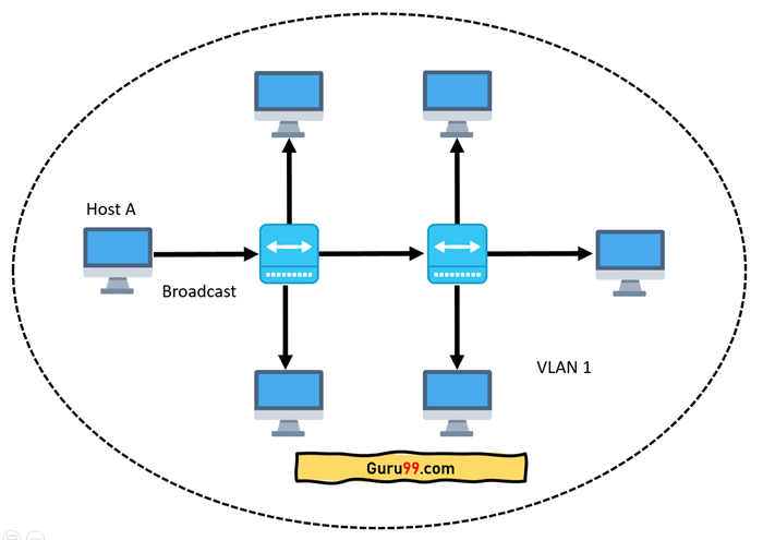
Without VLANs, a broadcast sent from a host can easily reach all network devices. Each and every device will process broadcast received frames. It can increase the CPU overhead on each device and reduce the overall network security.

In case if you place interfaces on both switches into separate VLANs, a broadcast from host A can reach only devices available inside the same VLAN. Hosts of VLANs will not even be aware that the communication took place. This is shown in the below picture:

VLAN in networking is a virtual extension of LAN. A LAN is a group of computer and peripheral devices that are connected in a limited area such as a school, laboratory, home, or office building. It is a widely useful network for sharing resources like files, printers, games, and other applications.

Here are step-by-step details of how VLAN works:

  • VLANs in networking are identified by a number.
  • A Valid range is 1-4094. On a VLAN switch, you assign ports with the proper VLAN number.
  • The switch then allows data which needs to be sent between various ports having the same VLAN.
  • Since almost all networks are larger than a single switch, there should be a way to send traffic between two switches.
  • One simple and easy way to do this is to assign a port on each network switch with a VLAN and run a cable between them.

Difference between LAN and VLAN

LAN

VLAN

LAN can be defined as a group of computer

and peripheral devices that are connected

in a limited area.

A VLAN can be defined as a custom network that is created from one or more local area networks.

The full form of LAN is Local Area Network

The full form of VLAN is Virtual Local Area Network.

The latency of the LAN is high.

The latency of VLAN is less.

The cost of LAN is high.

The cost of a VLAN is less.

In LAN, the network packet is advertised

 to each and every device.

In VLAN, the network packet is sent to only a specific broadcast domain.

It uses a ring, and FDDI (Fiber

Distributed    Data Interface) is a protocol.

It uses ISP and VTP as a protocol.

MULTIPLE VLANS AND SINGLE ROUTER

If you have a router that supports virtual LANs (VLANs), you can create multiple VLANs from that single router. This can be useful if you want to segment your network traffic for security or performance reasons.

A VLAN is a logical grouping of devices on a network. VLANs are used to segment a network into smaller, more manageable pieces. VLANs are created by configuring a router or switch to divide a physical network into multiple logical networks.

Creating a VLAN is a two-step process. First, you must create the VLAN itself. This is done by configuring a router or switch to create a new logical network. Second, you must add devices to the VLAN. This is done by configuring the router or switch to add devices to the VLAN.
Adding devices to a VLAN is a simple process. First, you must determine which devices you want to add to the VLAN. Second, you must configure the router or switch to add those devices to the VLAN.

Switches generate a VLAN as a broadcast domain. You, the administrator, set up some switch ports in a different VLAN than the default VLAN for the sake of convenience. VLANs are enabled in Cisco switches by default, and ALL devices are already connected to VLAN 1. If there were no additional configuration required, these devices would be unable to communicate. All devices on a switch can communicate with one another using the same ports as a single switch. Consider using VLANs if you’re having difficulty connecting to the Internet. A trunk port is shared by multiple switches or routers and is used to route traffic between them.

VLANs can be configured in a variety of Cisco switches, even if they are in different models. To communicate with other trunks, a trunk port must use a special trunk trunk protocol. Because VLANs limit the number of broadcasts, they provide a higher level of performance to large and medium LANs. As a result, they also provide security because you effectively have one group of devices connected to a VLAN.

MULTIPLE VLANS WITH SEPARATE MULTIPLE ROUTERS

It is possible to use multi-VLAN ports to conduct networking. These switches and routers can be used to separate groups of users, departments, and functions from one another without the need for separate switches or routers. There is a significant cost savings, improved network security and performance, and simplified management associated with this model.

PROCEDURE

  1. Create a simulator object
  2. Open a nam trace file and define the finish procedure then close the trace file, and execute nam on the trace file.
  3. Create VLANs with router(s) that form a logical network
  4. Create duplex links between the VLANs
  5. Schedule events and run the program.

Scheduling Events

NS is a discrete event-based simulation. The TCL script defines when the event should
occur. The initializing command set ns [new Simulator] creates an event scheduler, and events are then scheduled using the format:

The simulation can then begin using the command

$ns run

PROGRAM

set opt(tr)        "vlandemo.tr"

set opt(namtr)     "vlandemo.nam"

set opt(seed)        0

set opt(stop)        1.0

set opt(node)        4

set opt(qsize)        100

set opt(bw)        10Mb

set opt(delay)        1ms

set opt(ll)        LL

set opt(ifq)        Queue/DropTail

set opt(mac)        Mac/Csma/Cd

#set opt(mac)        Mac/Csma/Ca

#set opt(mac)        Mac/802_3

set opt(chan)        Channel

set opt(tcp)        TCP/Newreno

set opt(sink)        TCPSink

set opt(app)        FTP

proc finish {} {

        global ns opt

        $ns flush-trace

#        exec nam $opt(namtr) &

        exit 0

}

proc create-trace {} {

        global ns opt

        if [file exists $opt(tr)] {

                catch "exec rm -f $opt(tr) $opt(tr)-bw [glob $opt(tr).*]"

        }

        settrfd [open $opt(tr) w]

        $ns trace-all $trfd

        if {$opt(namtr) != ""} {

                $ns namtrace-all [open $opt(namtr) w]

        }

        return $trfd

}

proc create-topology {} {

        global ns opt

        global lan node source node0 nodex

        set num $opt(node)

        for {set i 0} {$i< $num} {incri} {

                set node($i) [$ns node]

                lappendnodelist $node($i)

        }

        set lan [$ns make-lan $nodelist $opt(bw) \

        $opt(delay) $opt(ll) $opt(ifq) $opt(mac) $opt(chan)]

        set node0 [$ns node]

        $ns duplex-link $node0 $node(1) 20Mb 2ms DropTail

#        $ns duplex-link-op $node0 $node(1) orient right

        set nodex [$ns node]

        $ns duplex-link $nodex $node(2) 20Mb 2ms DropTail

#        $ns duplex-link-op $nodex $node(2) orient left

}

## MAIN ##

set ns [new Simulator]

settrfd [create-trace]

# create-topology

set tcp0 [$ns create-connection TCP/Newreno $node0 TCPSink $nodex 0]

$tcp0 set window_ 15

set ftp0 [$tcp0 attach-app FTP]

#set udp0 [new Agent/UDP]

#$ns attach-agent $node0 $udp0

#set cbr0 [new Application/Traffic/CBR]

#$cbr0 attach-agent $udp0

#set rcvr0 [new Agent/Null]

#$ns attach-agent $nodex $rcvr0

#$udp0 set dst_ [$rcvr0 set addr_]

$ns at 0.0 "$ftp0 start"

#$ns at 0.0 "$cbr0 start"

$ns at $opt(stop) "finish"

$ns run


# to run the example, use the following line

$ ns filename.tcl

$ nam vlandemo.nam

OUTPUT

VLAN in ns2
VLAN Demo


09 January 2024

HTTP and FTP Simulation in NS2

HTTP and FTP Simulation in NS2


HARDWARE / SOFTWARE REQUIRED:

  • Network Simulator-2
  • Operating System – LINUX (UBUNTU)

THEORY:


HTTP:

  • HTTP stands for Hypertext Transfer Protocol.
  • It is a protocol used to access the data on the World Wide Web (www).
  • The HTTP protocol can be used to transfer the data in the form of plain text, hypertext, audio, video, and so on.
  • This protocol is known as HyperText Transfer Protocol because of its efficiency which allows us to use it in a hypertext environment where there are rapid jumps from one document to another document.
  • HTTP is similar to FTP as it also transfers files from one host to another host. However, HTTP is simpler than FTP as HTTP uses only one connection, i.e., no control connection to transfer the files.
  • HTTP is used to carry the data in the form of a MIME-like format.

Features of HTTP:

  • Connectionless protocol: HTTP is a connectionless protocol. HTTP client initiates a request and waits for a response from the server. When the server receives the request, the server processes the request and sends back the response to the HTTP client after which the client disconnects the connection. The connection between client and server exists only during the current request and response time only.
  • Media independent: HTTP protocol is media independent as data can be sent as long as both the client and server know how to handle the data content. It is required for both the client and server to specify the content type in the MIME-type header.
  • Stateless: HTTP is a stateless protocol as both the client and server know each other only during the current request. Due to the nature of the protocol, both the client and server do not retain the information between various requests of the web pages.

HTTP

HTTP Transactions

Computer Network HTTP

FTP

  • FTP stands for File transfer protocol.
  • FTP is a standard internet protocol provided by TCP/IP used for transmitting files from one host to another.
  • It is mainly used for transferring web page files from their creator to the computer that acts as a server for other computers on the internet.
  • It is also used for downloading files to computers from other servers.

Objectives of FTP

  • It provides the sharing of files.
  • It is used to encourage the use of remote computers.
  • It transfers the data more reliably and efficiently.

Although transferring files from one system to another is very simple and straightforward, sometimes it can cause problems. For example, two systems may have different file conventions. Two systems may have different ways of representing text and data. Two systems may have different directory structures. FTP protocol overcomes these problems by establishing two connections between hosts. One connection is used for data transfer, and another connection is used for the control connection.

FTP

Mechanism of FTP

The above figure shows the basic model of the FTP. The FTP client has three components: the user interface, the control process, and the data transfer process. The server has two components: the server control process and the server data transfer process.

There are two types of connections in FTP:

Computer Network FTP

Control Connection: The control connection uses very simple rules for communication. Through control connection, we can transfer a line of command or line of response at a time. The control connection is made between the control processes. The control connection remains connected during the entire interactive FTP session.

Data Connection: The Data Connection uses very complex rules as data types may vary. The data connection is made between data transfer processes. The data connection opens when a command comes for transferring the files and closes when the file is transferred.

FTP Clients

  • FTP client is a program that implements a file transfer protocol that allows you to transfer files between two hosts on the internet.
  • It allows a user to connect to a remote host and upload or download the files.
  • It has a set of commands that we can use to connect to a host, transfer the files between you and your host, and close the connection.
  • The FTP program is also available as a built-in component in a Web browser. This GUI-based FTP client makes the file transfer very easy and also does not require remembering the FTP commands.

ALGORITHM:
1. Create a simulator object
2. Open a nam trace file and define the finish procedure then close the trace file, and execute nam
     on the trace file.
3. Create two nodes that form a network numbered from 0 to 1
4. Create duplex links between the nodes n(0) to n(1)
5. Setup TCP Connection between n(0) and n(1)
6. Apply FTP Traffic over TCP.
7. Schedule events and run the program

PROGRAM

This script is created by NSG2 beta1

#===================================

#     Simulation parameters setup

#===================================

setval(stop)   10.5                         ;# time of simulation end

#===================================

#        Initialization        

#===================================

#Create a ns simulator

set ns [new Simulator]

#Open the NS trace file

set tracefile [open httpex.tr w]

$ns trace-all $tracefile

#Open the NAM trace file

setnamfile [open httpex.nam w]

$ns namtrace-all $namfile

#===================================

#        Nodes Definition        

#===================================

#Create 6 nodes

set n0 [$ns node]

set n1 [$ns node]

set n2 [$ns node]

set n3 [$ns node]

set n4 [$ns node]

set n5 [$ns node]

#===================================

#        Links Definition        

#===================================

#Createlinks between nodes

$ns duplex-link $n0 $n2 100.0Mb 10ms SFQ

$ns queue-limit $n0 $n2 50

$ns duplex-link $n3 $n2 100.0Mb 10ms SFQ

$ns queue-limit $n3 $n2 50

$ns duplex-link $n1 $n2 100.0Mb 10ms SFQ

$ns queue-limit $n1 $n2 50

$ns duplex-link $n3 $n4 100.0Mb 10ms SFQ

$ns queue-limit $n3 $n4 50

$ns duplex-link $n3 $n5 100.0Mb 10ms SFQ

$ns queue-limit $n3 $n5 50

#Give node position (for NAM)

$ns duplex-link-op $n0 $n2 orient right-down

$ns duplex-link-op $n3 $n2 orient left

$ns duplex-link-op $n1 $n2 orient right-up

$ns duplex-link-op $n3 $n4 orient right-up

$ns duplex-link-op $n3 $n5 orient right-down

#===================================

#        Agents Definition        

#===================================

#Setup a TCP connection

set tcp0 [new Agent/TCP]

$ns attach-agent $n0 $tcp0

set sink3 [new Agent/TCPSink]

$ns attach-agent $n5 $sink3

$ns connect $tcp0 $sink3

$tcp0 set packetSize_ 1500

#Setup a TCP connection

set tcp1 [new Agent/TCP]

$ns attach-agent $n4 $tcp1

set sink2 [new Agent/TCPSink]

$ns attach-agent $n1 $sink2

$ns connect $tcp1 $sink2

$tcp1 set packetSize_ 1500

#Setup a UDP connection

set udp4 [new Agent/UDP]

$ns attach-agent $n2 $udp4

set null5 [new Agent/Null]

$ns attach-agent $n5 $null5

$ns connect $udp4 $null5

$udp4 set packetSize_ 48

#===================================

#        Applications Definition        

#===================================

#Setup a FTP Application over TCP connection

set ftp0 [new Application/FTP]

$ftp0 attach-agent $tcp0

$ns at 1.0 "$ftp0 start"

$ns at 10.0 "$ftp0 stop"

#Setup a FTP Application over TCP connection

set ftp1 [new Application/FTP]

$ftp1 attach-agent $tcp1

$ns at 1.0 "$ftp1 start"

$ns at 10.0 "$ftp1 stop"

#Setup a CBR Application over UDP connection

set cbr2 [new Application/Traffic/CBR]

$cbr2 attach-agent $udp4

$cbr2 set packetSize_ 48

$cbr2 set interval_ 50ms

$cbr2 set random_ null

$ns at 1.0 "$cbr2 start"

$ns at 10.0 "$cbr2 stop"

#===================================

#        Termination        

#===================================

#Define a 'finish' procedure

proc finish {} {

global ns tracefilenamfile

    $ns flush-trace

close $tracefile

close $namfile

execnamhttp.nam&

exit 0

}

$ns at $val(stop) "$ns nam-end-wireless $val(stop)"

$ns at $val(stop) "finish"

$ns at $val(stop) "puts \"done\" ; $ns halt"

$ns run


NS2
NS2 Simulation

NS2
NS2 Output


Powered by Blogger.

About Me

Featured Post

5G Network Simulation in NS3 using mmWave | NS3 Tutorial 2024

5G Network Simulation in NS3 Using mmWave This post shows the installation of ns3mmwave in Ubuntu 24.04 and simulates 5G networks in ns3. In...

Contact form

Name

Email *

Message *

Total Pageviews

Search This Blog

Pages

Pages

Pages - Menu

Most Popular

Popular Posts